Project Introduction (Maya research 3D)
What is 3D modelling? 3D modelling is any computer generating graphic software which allows you to manipulate three dimensional shapes/ models. Manipulating a shape is called modeling. The process of which the software does this is by a mathematical representation of surface or an object like geometry of the object. (This could be an either an living or inanimate)the word modeling requires many element that make up the object but in relation to the software these are called rendering, sculpting. Their are two forms of 3D modeling these are called solid, and shell boundary. Solid modeling is defined by the volume of an object e.g. (like a rock) this is mostly used for engineering, medical simulations. Shell boundary are models that are represent the surface of an object the boundary of the object not its volume of the object e.g. the mass. this process is mostly used in games and films. e.g. for games their used skin on a subject.
How is modelling for game different from modelling for films or any other medium? One of the huge and most obvious differences between the two is ever present polygon budget that’s found in any game development process. when it come to movie there’s not really a limit on the amount of polygons that can be in the given model than their is on games. like any other production, in movies you’ve got free range to use however many polygons it takes to get the model look good on screen because really that that what matters the most. but for game it is different you are limited by the power of the game engine and the hardware that is being played on.
What is hard surface/ organic modelling? hard surface modeling refers to what types of object you are modeling e.g. for hard surface (inanimate objects) things like cars, armor, weapons and architectural elements. For organic modeling it is things like characters, animals, creatures basically anything that is considered living is organic and anything for hard surface is inanimate.
What is environment modelling? environment modeling is the creation and the use of mathematical models of the environment using a three dimension software to create structures or objects .e.g. like Maya. and modeling some objects to make up the environment. e.g. tree to make up a forest.
What is modular modelling and unique modelling? modular modeling is where you can use a couple of structure e.g. (2) to make up a building up a building, and you can used the same object or structure over and over again in the game. As you can see in this from the example.The opposite to to modular modeling is unique modeling which is self explanatory is creating a modeling that can be replicate e.g. a person for example because people have different feature that make up that individual like the body structure, face nose mouth, eye’s mouth etc. This is unique modeling and these are the different between them.
here’s an example of modular modeling.

here’s an example of unique modeling. 
what is high poly modelling and low Polly modelling?
The differences between high poly and low poly models are how many polygon that the image as you can see from these images the first one has a low polygon count while the second image has more detail in to the hand and has more polygons. the more polygons the more detail can be put in to an object or a character.

what is the different modelling software? The different modeling software you can accesses thought an number platform is ,3D Studio Max,AutoCAD,Lightwave 3D,Autodesk Maya,Photoshop CC,Rhinoceros,ZBrush.
Terminology 3D (keywords)
what is the modelling terminology?
Vertex- are the corners or points of the shape.
Edge- are the side of the shape.
Face- is the area surface of the shape.

-any additional and relevant researched on going terminology
2D research
What are UV’s?
UV mapping stands for the technique used to wrap an 2D image texture into 3D mesh.basic where you project a 2D image on a 3D model.
what is 0-1 UV space? The UV space is your 2D net for putting texture on to your mesh. (It is the work space inside the grid.)

working inside and outside the UV space. you can work outside and inside the UV space. Working in the UV space will allow the object in question to have more of a high resolutions geometry that working outside the UV space. You would normally work inside the UV space if you are modeling some unique like a character.If you are working outside the work space you would model things that can be replicate like objects or structures.
Different UV software and methods? The different types of UV software are ,Marmoset Toolbar, UVs/Mapping, Remesh/Retopology, Map Generation/Baking,3D Painting, Zbrush, belnder. These are the different types of mapping, mapping UVs, automatic UV mapping, spherical UV mapping, cylindrical UV mapping, planar mapping.
what is spherical UV mapping? Spherical mapping, is where their project UV’s on to shape that is based on a spherical shape, and wraps around the mesh.This projection is best for shapes which can be completely enclosed and visible within a sphere, without projecting or hollow parts. … Note: Projection mapping only works properly on a single object at a time.
how you do you do spherical mapping on Maya? To create UV’s using a spherical mapping technique for Maya software.These step by step instructions on how to do the three types of mapping.
- 1)First of all you will need to select the face you want to project the UV onto
- 2) Then select UV then spherical mapping in UV interface (option)
- 3)Use the manipulator to change the size and the position of the object of the object in (this case the sphere)
- 4) Finally use the UV editor to view and edit the resulting UV’s.
here is references to source: (Hyperlink’s) https://knowledge.autodesk.com/support/maya/learn-explore/caas/CloudHelp/cloudhelp/2016/ENU/Maya/files/GUID-2B74F60D-B6B5-4794-BDC1-17E2FB06F393-htm.html, https://knowledge.autodesk.com/support/maya/learn-explore/caas/CloudHelp/cloudhelp/2018/ENU/Maya-Modeling/files/GUID-CD17C2C5-A442-4960-91DB-A2E5099EBF61-htm.html
This is the same process for all different types of UV mapping not just spherical mapping. same process for cylindrical UV mapping, spherical, and planar mapping
what is cylindrical UV mapping? Cylindrical mapping creates a UV’s projection for an object based on a cylindrical shape and that gets wrapped around the mesh of the shape in (this case a cylinder). This projection is best for shapes which can be completely enclosed and visible within a cylinder, without projecting or hollow parts. … Otherwise, perform a projection on each object separately.
what is automatic UV mapping? Automatic mapping creates UV’s for a polygon mesh by attempting to find the best UV placement by simultaneously projecting from multiple planes. This method of UV mapping is useful on more complex shapes where the basic planar, cylindrical, or spherical projections do not produce UV’s that are useful, especially on components that project outwards or are hollow in nature. Automatic UV mapping is where it take picture from all sides of the object and find the best surface to project the texture on to the mesh.
What are texture maps in games? you shouldn’t really notice low resolution geometry when playing a game. Use Transparency Maps An alpha, or transparency map, is one of the best ways to create the illusion of detail, and is a widely used texturing technique in video games.
what are materials in games? Materials is the based of the object. the textures are what is a applied to the martial to give it look from its colour, transparency , displacement, brightness, these are the texture maps for the object that are layered to give it that texture. The way to distinguished from the material as 0-1 binary code for e.g. the material can only be one or the other 1-0. You can go 0.5 if the material is a mixture between the two materials this is called blending textures, which is used frequently in games. e.g. A man made build with vines growing on the side of the building and plants engulfing the structure.
PBR- physical based rendering
0-non metal
1-metal
(image example below)
what are transfer map? Transfer maps is an editing tool in 3D modeling software, used to create various types of texture maps. The Transfer Maps editor can only generate texture maps for polygonal geometry. By default, if multiple target objects are loaded in the Transfer Maps editor, then a single map is generated for all the target.
what are texture map’s?A texture map is an image that is projected on to a surface or a shape, polygons.
This is an image of the transfer map tool from a 3D modeling software. As an example.

texture/UV terminology. (key words )
Practical Research
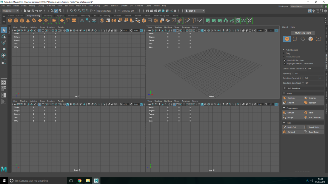
Their are many different element to Maya and menus / sub menus as you can see.
These menus are:
- Top menu (File, edit, create etc.)
- Status line – switches a menu set (e.g. modeling, animation, rigging etc.)if you notice the Top menu will change.
- Shelf is relevant to the common things you will mostly use. The shelf is the one with the cube, sphere, cylinder, etc. you can select other option on the shelf such as polygons which is the main menu you will be using. and curves, sculpting rigging, animation.(etc). You can also change options elements by the status line. When you click on one of these menus on shelf other options come up depending on what menu you have clicked. The most common shelf you will be using is polygon shelf .
- Channel box/layer editor of you have a object in you work space it gives us the status of that object that is in the work space. e.g. you can see the position x,y and z on the bar menu at the side of Maya.
- Attribute editor select your object then click the icon with three rectangles and that will open up you attribute editor. This menu gives all attribute to your object that you currently have selected.
- Tool settings/modeling tool kit is related to you tool setting it give you option for them to change you setting for you tools in the tool box you click the icon three dot icon located right, top where your status line is. the tool setting will open up on the left where the tool box is.
- Time line/ range slider
- Command line/ help line
- Tool box is for manipulating the object and allows you to scale,rotate, and move you object in the work space using the tool box at the side underneath where the shelf.


If you select the cube icon on the shelf a cube will appear in the center of the work space/grid. As you can see from the image displayed up above. you can create other shape just by tapping the icon, on the shelf menu. you can also change the shelf via menu set.
-watch Maya into videos
-follow and do each video
-Record progress via blog

1)This image came cross my attention by how simplistic it is but at the same time how stylish it looks due it being a fantasy theme building and it something you would see in that kind of world mix with Japanese influences that has been added to it e.g. the cherry blossom tree.

2)This is more of a complexed and intricate design of a steam fantasy type building. I like how intricate and the design of it has a steam but at the same time an apocalypse style building that you would see.
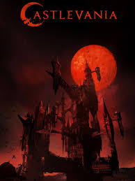
3)This is an image of a 17th century castle from the game series castlevania. Dracula castle. This would have very interacted build structured I like the gothic dark horror theme and the architecture of castle and their designs.

4)The image of this steam punk/ futuristic floating building would have alto of complexes patterns engraved into the building and other bits coming off it and many other details.

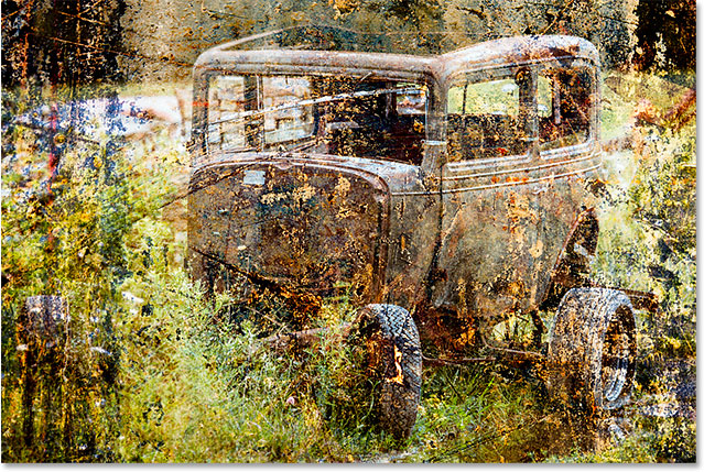
5)This picture is of a castle that as sharp jagged structure of an old ancient castle around 16th to 17th century with like the dark a horror, gothic theme.
I feel as if this would be achievable to model some that is not to intricate but as well simplistic. It as a basic design and the shapes are easy replicated in the modelling software. I like nature aspect of the build.

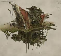
6)This image looks simply but would struggle of how much there is to model, the reason why I like it looks similar to a traditional Japanese house.

7)I also think this in is simplistic and really could be achieve able in the time frame that we have been given. I like the design it remains me of nightmare before charismas art style.

8)This would take more modelling individual pieces to model this 16th to century style Victorian, I like the simplicity and the design makes it dark themes.

9) Old English 15th hundreds building, this as basic geometry so this would be a suitable to model and can be broke down the part of the house to build it up. Not to intricate and it’s a design simply and structure. The reason why I was drawn to this building in particular is the style and the character that the building has.
10) I feel as if this would be achievable to model some that is not to intricate but as well simplistic. It as a basic design and the shapes are easy replicated in the modelling software. I like nature aspect of the build.
The five that I have narrow it down to are (9,7,5,6,10) these one that I have pick that I like the design of and the structure.
Arrow it down to 3 concept art of buildings.
The three that I have chosen are is 7,3 and 6.
6)concept six is a Japanese’s traditional style tower that is similar to the pagoda which is a Buddhist temple, it is a multi stack level which bears a resemblance to the concept art and the arts that design the art is inspired by old traditional style type template and has turned it into a house, in his design with a garden and extensions to the house, the time it would taker to model all of the individual pieces of the garden and exertions of the house would be time consuming i think i would just managed the build as it stand without the garden on over unique parts to this concept art meaning it would take me longer to model.
3) My other concept that I have chosen is a castle which is from the popular video game series castlevania this is Dracula castle in the Netflix series of castlevania, this as a heavy influenced dark gothic architecture, and a horror style to it. this castle see as it is complex in architecture and as got really depth and detail to it and looks really intricate and it not just one big structure it as many structures attracted to it like bridges to other towers to the castle, this would require a lot of work and time just to model it and get the basic structure and get it how you want it, that is without all the other detail that individual pieces that have to be added the basic of the model this would be way beyond my skills of model see I have just started to use and try to get the hang of Maya and to be honest I don’t think I would be able to finish in the deadline that has been give which is 5 weeks.
How to setup to do uving with (2018 Maya) How to UV with Maya 2018 software?
To start with to make sure your setup for UV to go to left hand side bar where the toll box is located down from that you will see many different square icons these icon can change views so you are looking at the object in different views. Click on the first icon, square with 4 squares in it then hold right click a little menu will come up. then go down to the option that say ‘two plane side by side’ and you will see that your screen has split into two one will have a top down view and the other view is three dimensional view of your object. this is the setting on default. 
Next go to panel which is under the shelf when you have clicked panel should come up with a min menu click perspective on the menu that come up go over to the option persp 1 and persp and swap the screens around so you have the top top view on the right that your perspective view of you build on the left. go on to the left screen click panels under the shelf a min menu should pop up go down to panel click it and another menus should come out of the other menu then scroll down to UV editor then click it. (here an image below to show this.)

Next go on to the UV editor screen go on to tools at the top of UV editor where it say edit create etc. click tool then go down to show UV tool kit and the UV tool kit should pop up. then grab the UV tool kit menu them drag it in to the bar at the right hand side where your other menus are to easy access your menus and organize them.By going on to the icon with 4 square in it under the tool box press right click on it go down to save layout and called it what ever you want i saved it to (new layout 1) then click save and that should have saved your current layout of Maya. (seen the image below.) 
Now that that is set up the first thing you will do next is if you would look at the uv editor screen and the UV tool in the bar at the far right of screen he are lots of drop menus, what you want to click is planar in create menu bar but.first make sure your hole of your build is selected. this dose not relate to the building not at all.Or click on any bit of your build e.g. image below. this planar is much more easy that automatic and more preferable to used for what we are doing you can do it as a hole but it will be difficult to distinguishes what part is what for your build so keep it simply.

next what you want to to is shift and left click on planar map option a menu should come up which is the planar mapping option box.it is really important that you have the this option click (on keep image width/height ratio) if it was off e.g.and you do your planar map you will see that the house is squashed,and the project crop to the house and that squashed it to my 0-1. (As you see from the image below.)
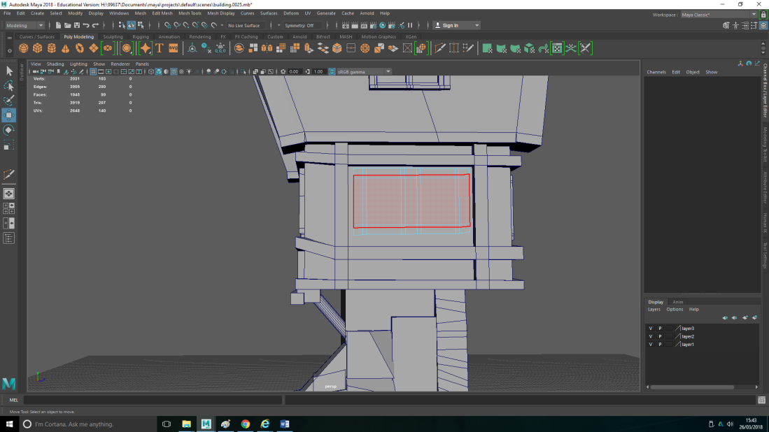
 By using the project is look at the concept and look to see if their are any of the same kind of textures. press alt and H to hide the thing that are in the way of the wall. select the faces of that wall that you want to keep. then go over to the UV editor to planar then left click on planar and that will project that wall. At the moment you can see it is red. If you go up to the icon at the top of the UV editor screen with the three squares and click that you will see the wire frame. if i left click it is red and if i right click it is multi colored for different UV shells. Just do left click because the (RED) is telling you it is the wrong way around. To make it the right way round go in to transform in you UV tool kit it is the one above create. then scroll down to where it say scale and their should be an option to flip click that and it should flip it and change it to blue so it is the right way round. make sure you select the hole of it. this (seen in images below.)
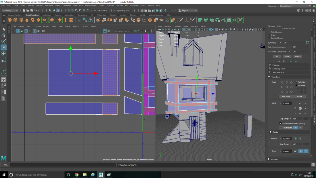
this image is references to how to get your UV mapping the right way around red is the wrong way and blue is the right way around. image shows you the option need to press to do this process.

Additional you want to do the same with all the face of you building by selecting it a face at a time and drag them to the 0-1 space on the UV editor. As you can see the scale is a bit wrong so what you want to do is go to transform option before that select the first UV mapping you did in you, next go to UV tool kit scroll down to where it say texel density you are going to click (GET) which record the information to the scale of the UV mapping. then select the other one and go on to set option near texel density, and that should be the right scale as the other one. then what we want to do it fit the UV mapping together to do this select the edge of them while their are close together.When all the edges are selected shift right click then a menu should come up then click (Move and sew edge). and it stitched it together.(Seen in images below.)


For separate thing that are attached to your building make sure thing are neat in the 0-1 space and sort things out like what texture are for what. (Seen in image below on left side.)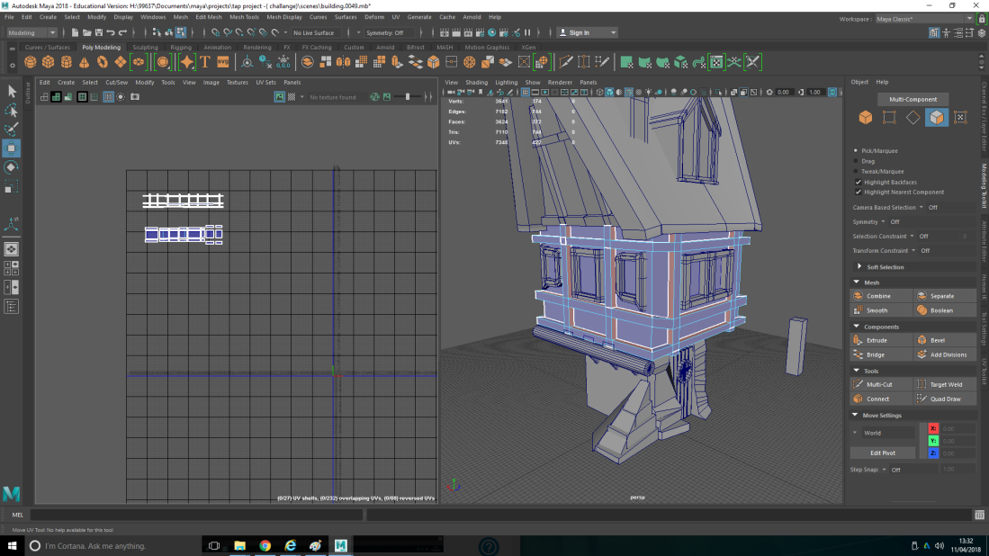
To unfold your object in to a net what you will want to do is select all the face of the object then shift right click to create UV shell to make sure you have got it all together their. then go to planar map right click to do the mapping of object. After that you want to get the corns of the object to it fold open shift then click edges and select the corner edges of the object. If you go to the UV at the top menu next to where it says deform next to their scroll down and click (3D cut and sow tool) what that doses if you double click the corns of the object e.g. it turns the edges corns white mean you are cutting they. If you (shift click) it will height light more that one white edge. To stop this (Ctrl click) to click on the edge you don’t want. when you have cut all the corns come over to your UV’s right click then (click UV) go to the UV tool kit then scroll down to find the unfold drop menu click that and their should be an option then under optimize to unfold click that. make sure the UV mapping is select in the UV editor screen, that you want to unfold. then shift right click on the UV editor screen then go to the option that as unfold at the side then click unfold, and should unfold. you will see if it is not straight go on to unfold option down to where it say straighten UV’s. Now you have them separated, you can move them ,manual get them to the right size then go down where it say align in the unfold drop down bar option you will see many different icons. the icon you want to press is the one with two rectangle facing down from a line that will straighten it out and (G) to repeat action. to move you UV’s select corners to move it as a whole. You want to make sure your 2D UV space is a good clean representations of your 3D space.
If that option doses not work the problem will most probably be if you turn on you checked pattern in UV editor screen the icon at the far left with black and white square in a square, turn that on and you will see that their is some stretching going on. if it starts to do things like this select the face in the center of your object and re planar map it, then select the UV’s and stretched it manual so it is not stretched then click set in the UV tool kit menu in telex density and should have set it. To move your other UV’s that make up the shape/ net is right click face shift then right click on to UV shell. Images seen below on how to do process to unfold your UV’s ans straighten them out. 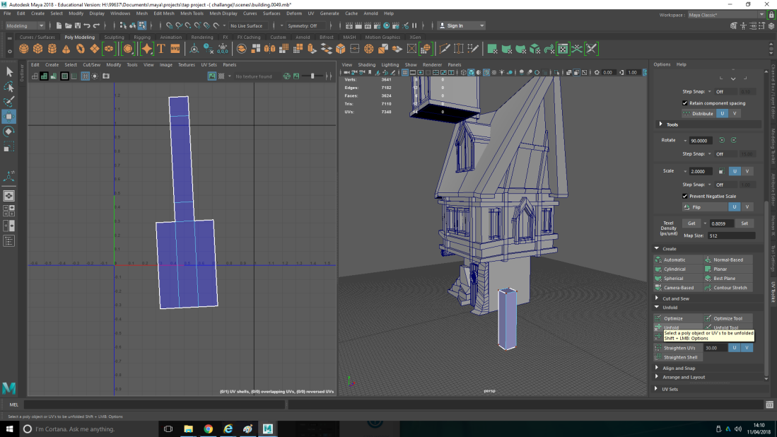


Assign materials/colour to my building
Select your UV’s of what you want to give it a material.Next you want to go the material attributes which is in your stasis line above the shelf, the little icon that is a sphere with a circle carved out of it click on that it should come up with a large menu. Right click on the highlighted object then go down to assign new material a menu should pop up go to Maya click surface, then go to blinn. Then you open up the hyper-shade which is the sphere with a carved circle out of it. go to blinn 2 rename it. Do this for every one of your UV’s. changes it colour to anything something you can see will get back to it in hyper shade select what you called your material go to colour and click it a menu should come up select your colour. come back to your 3D model you will see that your section that you have selected as turned that colour. (Seen in images below how to do process)


My cursor is on blinn which is the 8th on down in this image above this text.

you will see it change the colour of what you have selected from your UV’s.
 while UV mapping for planar if you (right click) it will take a side view of the mapping instead of a front view. to take a front view shot of your map (left click) on planar. (Seen in image above.)
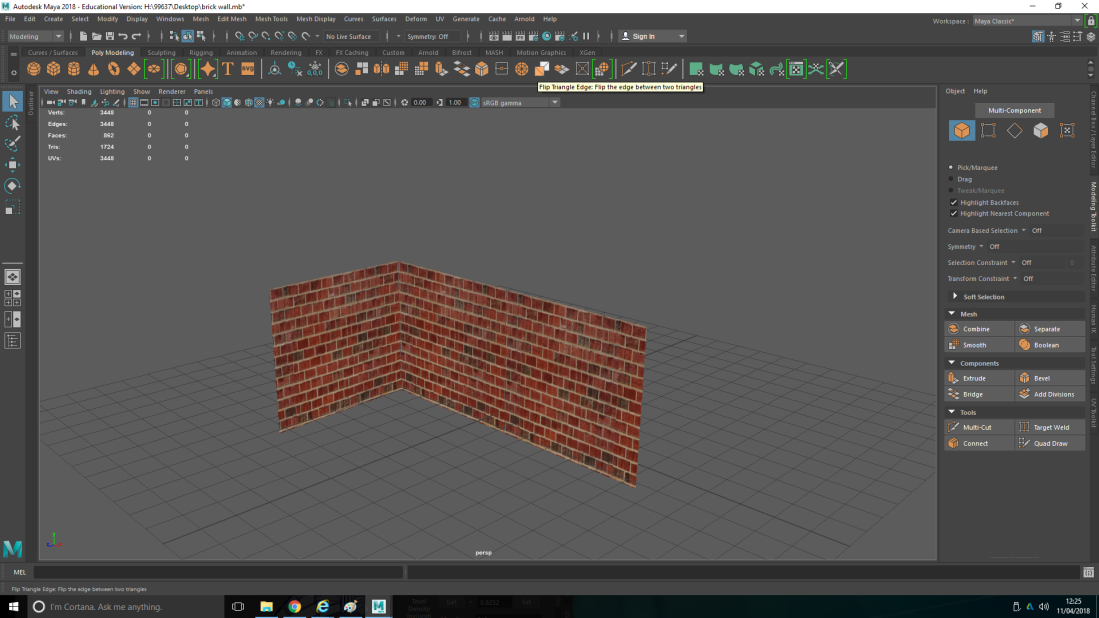
This screen shot above, is my first ever attempt to do UV mapping. It it a very simply UV mapping over a simply structure this has not bin rendered yet. This was just a practice and to try out UV for my first time of doing it. After that you will want to set you image format to Targa. And make sure you set your project to the right point before you do this process.
To set up your UV and texture on Photoshop.
Go to UV at the top of Maya under thew stasis line click on UV editor then select the 3D model before you do this so you can select your UV. next select your UV’s by right click go to UV on the min menu that come up then select your UV’s. go on to the icon that looks like a camera click that a menu should come up then make sure you set your image format to Targa. Before doing any of this make sure you set your project in the right place, by going to file and set project then set your project.


Make sure you set your project to the right file before doing this.
final decision and choice of what I want to model.
7)this is the one that i have chosen to model. the reason why it is simplistic and i fell like i can achieve a model like this with in 5 weeks. I like the Gothic dark style as well it look a bit like night mare before Christmas, and remind me of Mario odyssey cap kingdom, these theme like a lot.

Here is my plan show how I am going to start modelling my build/house. I have broken it down it to is basic geometry to see how I would model the base of the structure and the bridge that is attracted to the house.
you can customize your options and menus in Maya 2018 by hold in space you a menu will come up. you can mix a match you set a take some set off the display like animation set at the bottom and other option to do this hold down space a menu will come up. you are go left and display menus will come up that are currently being displayed. you can click on them and the option that you clicked on will not be displayed near the work space you can change the options at will. you can do the same with the side options e.g. attribute editor you can open up the tabs of the different options icons in the top right select tool, channel box/layer editor, modeling tool kit.you can also order these how you want in the right side of Maya by clicking and dragging them to how you want.
To get the polygon count up and top left of you work space you need to click on display and heads up display then go on to the option that says polygon count click that that it should appear top left to the work space. to view you projects in Maya click on file then project window here you can move where you want to save your project. set project option is just below here you can set it in your desktop or any where else. as long as it is accessible and can be easy got to via Maya. you can save it to any options you what. make sure you back up your work on hard drive.

As you can see form this image the polygon count appeaser at the top left.
on this side is where the side option are e.g. channel box/ layer editor you can drag them and change them to your liking. also you can open the option up by the icons at the top right of Maya then drag the window to the side wait until the side bar turns blue and drop the window in. This is an easy way of accessing your key tool options for Maya and what you will mostly be using.

as you can see for the image an easy way to find you project is to go on to file then scroll down and click on project windows s to access you project via Maya and see where you are saving your projects. project set is to set where you want to save your project to.

when you click on project window an window will come up , that looks a bit like this this. (picture below text ) is where you can view and find your projects. same for saving or send your project in a save place and where you can asses it. 
to be able to get a views of the entire shape press space bar don’t hold down.
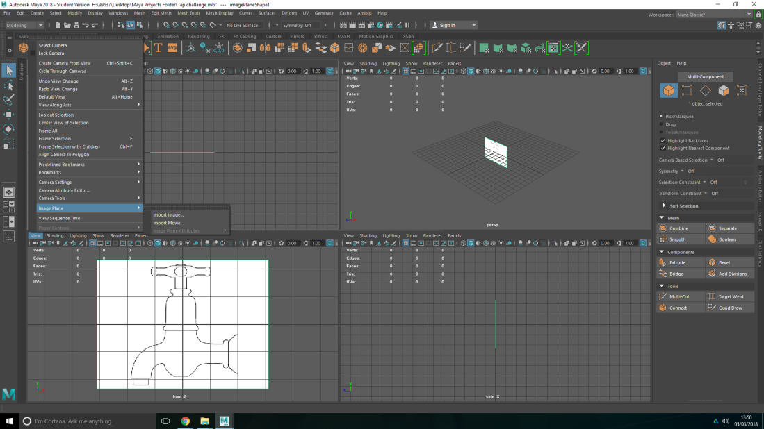 to get an image display on any of the view does not matter which one. click on view the go down to image plan then click important image form where the image you want in this case a tap template. as you can see for the picture then press F on the keyboard to frame it. as you can see from the image above. by doing this you have attached the image to the front view camera.
then scale your image by press R on keyboard or the icon on the tool box to scale the image.

after this step if you go into attribute editor on the right of work space. or via the icons at the top right. the window should come up displaying you image on the front view of the camera it will be called (imageplaneshape1) If you look down it will say display and have two options these being, view all or looking thorough camera click on looking thought camera option. when you click on this option you can only see it thought the front view camera. As you see form image.
 Next click on to the channel box/ layer editor. down at the bottom of the this option is the layers similar to Photoshop.
to make sure you do accidentally select the image a move it. select the image then go over to layer option at the bottom right then select the icon with square and dot, this adds select items to new layer.then click on layer 1 and a little menu should come up. that will come up and change the name to image plane then click save. Seen on you image below. then you have the image plane on layers options. you can turn it off on on by clicking the V and the third one along click twice until it say R meaning reference. now you will not be able to move the image while doing modeling and using it as a template because its been selected as a reference image so can not be move which is handy.

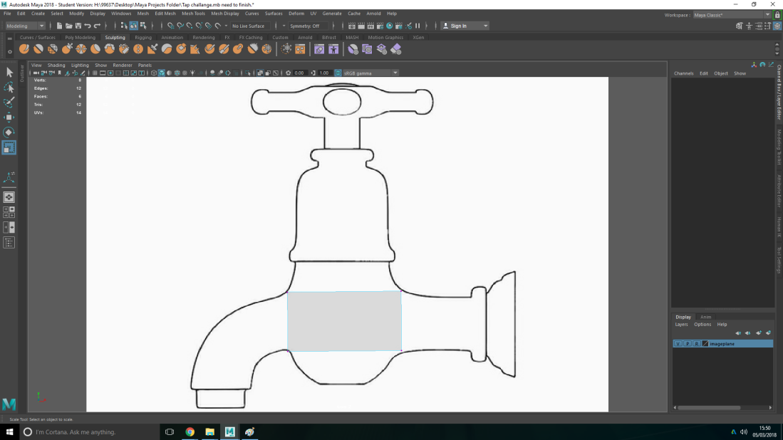
press select on the front view of the image then press space on keyboard to give a full screen of the image and can see it clearly. sen from the image below. we will be modeling this tap with a single cube and the ex strode tool which it the tool locate on the shelf its the icon that has a cuboid that has been stretched and squares surround it.

select the cube a it should appear in the middle of the image. Shown below here. 
to turn off grid press the grid icon below the shelf near work space. should look like square grid of 9 squares. Scale the square using scale tool in tool box or press R on key board. you see it covers over the image. We want to be able to see the image we could click the transparent square icon below near the shelf next to work space. but it disappears but if you go along to the icon where two squares over lap click that icon to make it see the geometry of the tap the square has faded to see image behind the square. 
drag square down to the bottom body of the tap. then go to the 3D view all view hold in right click then select vertex which are the corns of the shape allowing it to move it from the corns and stretch it. you can also see it on the front view. or you can go in to 2d and fit it to the template obvious using more that one square. As you can see where by these two images.
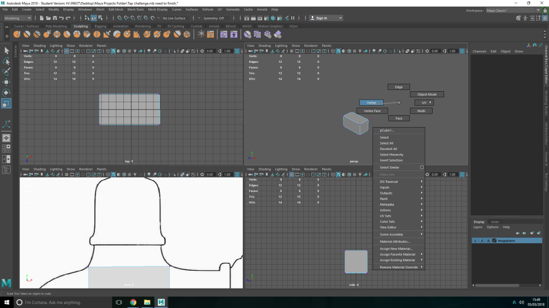
to be able to select faces simply hold right click and menu should come up then select faces this will only select the faces not the corns. you can draw a box on the front view to select certain face of the cube but recommend going to all perspective view which shows the shape as a hole. Image shown below.

Next to start extruding. for this you will want to go on to modeling tool kit at the side via click the icon or side bar with it on. then click the extrude icon make sure you have selected what face you want to extrude from by clicking the face. when you have extrude it should from another cuboid shape attached to it. click scale icon or press R. Remember to scale form the middle not where the arrows indicate the square in the middle to make the lines line up with tap template until you are satisfied and happy. Seen in image below.
don’t forget that you can extrude vertex of a shape and edges not just the face this it to tide up your model by having not a lot of detail. also move the vertex to where ever you want by pressing on key broad w.

To snap to verities when you want to snap it to a corn and get it in level with the other vertex that you have placed with your mouse. to snap to the same level ans the other verities that you have place. do this hold down v on keyboard drag it down. Place it near or close to the level that it is it should snap in level with other verities. just remember where ever you mouse Courser is hovering over it will snap to.

To be able to curve the shape around the object e.g. in this case tap where the water.enters out. Go to edged by holding down right click. highlight the two edges that are parallel to each other make sure you select back and front of the 3D object. you can hold hold shift to do this. After these are highlighted back and front of the shape, go to modeling tool then scroll to connect which is near the extrude tool and a green line should come up in the middle of the two edges that you have selected. next click in the middle mouse wheel and you will see more green line cutting it to sectors and becoming more curved and adds more in geometry.
It you hold down right click and go on to vertex face, your model will come part to see if you have any line under tow faces which counts as a face a could positional become a problem and take it out and delete it. its always good a clean model with out any extra edges or faces. Here seen in the image below. for example the image with a edged which counts as a face. Image references.


Other ways of telling their are more that one vertex taking up the same space is to highlight the verities and look in the polygon count graph to see how much verities their are no more that 1 verities in a space at a time. Way you can fix this it shift then right click go to merge verities at the top of the menu. you have three options first option is merges verities to center which bring them to the middle. target wiled tool that put the verities to a specific point. and the three option it the option that we want. click on this when you have selected it cuts the verities in half which takes care of that problem that we had early. A menu will come up called distance threshold, which merges the p the verities set it to 0.001 so solve the issue this it to make it set a stay so the extra verities that are in the same place as another one are no longer their.
Here is my model of my house so far , they are some issues that I have came across when modelling my building. One of them is merging vertex’s in Maya. hour lecture when thought it but I had forgot most of the menus to click. to merge vertex’s right click go on to vertex then highlight all the vertex in the object. then click shift and right click then click on to merge vertex then go on to merge vertices. this was but one problem I face when it came to modelling my building. Another problem

The issues that I had during when modelling my build is that I could not extruded some face od my model due to them being inverted faces which their appear black on Maya. This issues happened by me extruding the beans of my model individually here is an example:
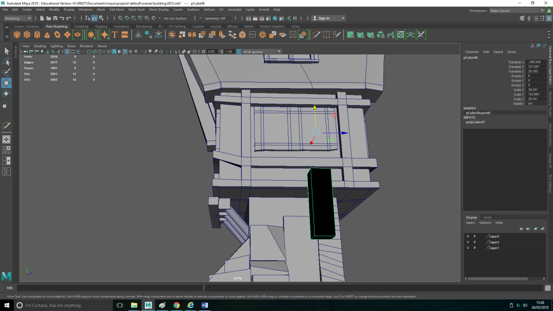
Here is an image of the following problem I had on my model. the black cube has been turned inside out, if you would put this on to a software engine it would not register it and come up with errors.
Other issues that I had is that faces on my model have overlapped thought each other. As you see here on the example above.
To fix these issues I decide it would be quicker and more efficient to remake and clean up the geometry of my model.
How I planned to do this is make a carbon copy of my pervious model by make an other cube and make that cube transparent by click the over lapped square icon under the shelf near the work space. move the cube to the reference and size it to the reference to make you previous model a reference is to go to channel box/ layer editor click on the icon that has a square and dot over it. click on that that will make a new layer over in the side bar menu in display at the bottom right. that click that change it to (R), which mean reference this cant be touch or moved while you re model your model. image example here.

After you have it the exact size as your previous model select the poor geometry and get it line up to how your previous model was. using snap (V) to snap the vertices to the reference model e.g. your pervious model so that it match your reference. then used the multi cut tool to add edge loops to match the beam do this first before the over step sorry mix it up. again snap the vertices to match the reference. the select the faces you want to extrude then extruded the beams out all together to keep the geometry clean.
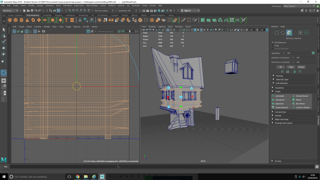
My old model had 1060 tris, and new model with clan geometry had 620 tris.

Where is a early design of my build.i started out on Photoshop to see the basic geometry of the build and start modeling the basic structure of the building.

I started to add thing to my build like door, windows, chimney, and other details only basic though so i know what it looks like. I then started using the connect tool to give the basic structure more geometry to copy off the concept art beams that it has on the building. Then i progress to using the extruding tool to extrude the buildings roof at the side as you can see from the image i try to copy the basic shape of the concept art and it’s geometry as close as possibly. Before i did that, i structure my house a bit more by making it look more jagged and rickety as you can see from the roof i select only the roof and then hold (right click) a click on vertex which are the corners of the shape. the i went to my tool box or press ![]() on the key broad to be able to manipulate the vertex and move it in any direction i want down, up or to the side to give it that rickety edge for the roof of the build just as it look in concept art.
on the key broad to be able to manipulate the vertex and move it in any direction i want down, up or to the side to give it that rickety edge for the roof of the build just as it look in concept art.

After i got all my geometry in place using the multi cut tool and connect tool i extruded my model different parts of it e.g the main structure itself to created the beams on the build leading up to side of the roof , as you see form the image. i did this by using the extruded tool which is found in modeling tool kit. when you have that menus up click on to the object you want to extruded hold in (right click) and a menus should pop up click on face this will allow up to select the face of that shape then go over to your extrude tool click on it and the x,y,z axes using the arrow can extrude in any direction until you are happy of how much they have extruded.

After extruding the main building started adding further detail like the window on the door the other thing that are separate from the building i also model these separate from the building. Final doing the the intricate detail to the model building.this is the final result.

here a screen shot of the final product. original this was supposed to be a house,that is connected to a bridge. but i did not have enough time to model that and the house and texture, UV them both so i decided to leave modeling the bridge as would take up to much time that i could be uving or texturing.
